ERROR MESSAGES and DEBUGGING TIPS
Table of Contents
The various types of errors
Editor errors
Compiler errors
Runtime errors
Errors in external routines
Locating an error in the MUSTIG graph
Debugging an error using the Probe mode
List of error messages
2 output pins connected by bifurcation
A module or a box must be selected first
An image window must stay at first level
Code too large
Compiler saturated : structure too complex
Data memory full
Data type not foreseen for this module (list of types)
End of file
External subroutine not found
File not found
First select a pin
Function not foreseen
Hierarchy not respected for the clustering module
Input format is incorrect
Jump module not connected
Length of variable forbidden
Library subroutine not found
Mixing signals with different characteristics along (variable name)
Mustig license does not exist on this machine
Number of pins is incorrect
Number of variables or variable name incorrect
Only one infinite (length = -1) variable is allowed
Open error
Operation not supported on a dynamic length variable
Operation on a variable which controls the length of another variable of the same signal (variable name)
Pin not connected
Read error
Respect hierarchy for images
Signal length not equal to a power of 2 (variable name)
Signal length not equal to a power of 2 + 1 (variable name)
Structure error
Structure not calculable
Syntax error
The box must have only one (entry) pin
The library cannot be saved this way (FileName.bib)
The signal does not depend on the variable (variable name)
The variable definitions must be static
This pin must be isolated with a "=" module
Too many windows
Try to loop a signal having a variable which length depends on the loop variable
Unknown code
Vicious circle
Write error
DEBUGGING TIPS
Some wires disappear, the graph looks inconsistent
I cannot print any Mustig window
The Cut / Paste facility does not work properly with other applications
All the windows of all the macros opened at a time !
The results do not update
All the graphical results are in black and white
I cannot drag a module from a Mustig window
The options file is not saved when exiting Mustig
The program shortcuts (File menu) do not work
The option I have set is not taken into account, or is not accepted
There are some graphical artifacts in the MUSTIG windows
Only a portion of a curve is displayed
MUSTIG ERROR MESSAGES and DEBUGGING TIPS
The various types of errors
Three types of error are likely :
- Editor errors :
occur immediately after an action (sometimes only a simple beep occurs)
- Compiler errors :
occur after a calculation has been asked, when MUSTIG tries to compile the graph into machine code,
- Runtime errors :
occur when running the compiled code.
Editor errors
If an invalid operation is performed by the user (e.g. connecting two outputs together), the error is immediately spotted by MUSTIG and an error message is displayed.
If the operation is valid but cannot be performed (e.g. dropping the image of a module into a panel too small to contain it), a beep occurs and the operation is simply cancelled.
Compiler errors
Most compiler errors occur when you have programmed an invalid operation, e.g. if you add two signals which do not have the same attributes, or if you connect two output pins together.
Compiler errors are generally detected when you launch a simulation. However, compiler errors leading to an inconsistent graph (e.g. two outputs connected together, error in a Formula module) are detected straight away.
Runtime errors
They are likely to occur at runtime. See list of error messages for a complete list.
Errors in external routines
Be aware that MUSTIG only checks its own code ! If an error occurs in an interfaced external routine, it will produce unpredictable results and could as well hang the computer. You should thus make sure to carefully check your source code.
The most frequent case of "mysterious" fatal errors in external routines is a segmentation or memory allocation fault lurking somewhere in the source code.
Our advice : Protect your code (at least the prototype versions) by adding extra verification routines and return an error message to MUSTIG via the r string pointer when an error is detected. In particular, the return value of any memory allocation function or system routine should always be checked.
Locating an error in the MUSTIG graph
When MUSTIG detects an error, the compilation or execution of the program stops and the module in which the errors has occurred is shown with a red frame. Click on the OK button in the error message display window to start debugging your application.
If the error is located inside a macro, the macro is shown with a red frame. You may then double-click on this macro, and then on the other red-framed macros until you eventually reach the erroneous module.
You may also use the Alt+I shortcut to successively open the selected macros. Using Ctrl+I instead of Alt+I closes the mother-window each time a module is opened (Windows only).
Once the error is found, you may try to solve it using the indications listed below.
Debugging an error using the Probe mode
Once the defective portion of the graph has been located, if the error is not obvious, you may want to learn more about the data at this point in order to detect the error. A good solution is to use the Probe mode.
The Probe mode works with any module, macro or box having only one input pin and no output pins. Any group of modules can be gathered into a box having only one input pin and no output pins, and then used in Probe mode. The box should NOT be connected to the graph.
The following example boxes are suitable for probing the graph :
|
|
|
|
 
|
Displays the type of data and the variables (name and attributes) carried by the wire to which the module is connected (see Getting general information about the variables) :

This allows to detect conflicts between the attributes (length, origin, sampling rate, etc) of the variables at various points of the graph. |
|

|
Displays a vector depending on variable t graphically (see Displaying 1D signals) |
|

|
Displays a matrix, or a cluster of 1D signals, depending on both variables t and x (see Displaying 2D signals) |
|

|
Calculates and displays the spectrum of a signal depending on variable t. |
Make sure the box is not connected to the graph, select it by clicking on it, and then run the Calculations / Probe command (Alt+R shortcut). The mouse cursor changes to a probe. Click on a wire : the selected probe box is implicitly connected to the graph and calculated. Click on another wire to see other results.
If the probe box uses one or more variables, the signal on the wire to which the probe is plugged in must depend on these variables.
Hit Alt+R again to leave the Probe mode.
A subsequent Alt+R with no box selected enters the Probe mode using the last used probe box.
List of error messages
2 output pins connected by bifurcation
Meaning : Two output pins are connected together with no intermediate operator, the graph is thus inconsistent.

Remedy : Disconnect one pin, or add an operator.

A module or a box must be selected first
Meaning : The command you have launched (open, probe, run, ...) operates on a macro. This macro must first be selected by clicking on it.
Remedy : Click on the macro on which the command should be performed and launch the command again.
An image window must stay at first level
Meaning : You have tried to slide an Image MUSTIG module into an image window or into a macro. This is not possible.
Remedy : The Image MUSTIG modules must be sled into the main program window and remain there. They cannot be copied or moved into macros, graphical windows or image windows.
Code too large
Meaning : The calculation of the results requires a code table larger than that allocated by MUSTIG.
Remedy : Click on the main program window. - Launch the Calculations / Clear the box command - Increase the value in the Edit / Options / Calculations / Size of program code (Kbytes) field. - Try running your program again. - If necessary, exit MUSTIG, rerun it and increase the value in the Edit / Options / Calculations / Size of program code (Kbytes) field before running your program.
Compiler saturated : structure too complex
Meaning : This error denotes an overflow in the internal stack of the compiler.
Remedy : If there exist an Edit / Options / Calculation / Stack size option, try increasing its value. Otherwise report this error to the online help service.
Data memory full
Meaning : The amount of memory allocated for data processing is not large enough. This error may also occur if you try to carry out on an infinite signal an algorithm which cannot run in real time, like in the example below (in this case there is no remedy, because the algorithm just cannot work !).

Remedy : Follow this procedure to increase the amount of data memory :
- Select the whole program by clicking on the main program window.
- Launch the Calculations / Clear the box command to clear the memory.
- Increase the Edit / Options / Calculations / Size of data (Kbytes) value (default value is 2Mbytes). The new value must be entered in kilobytes (e.g. 20000 = 20 Megabytes of data memory).
- Check that the new value has been accepted (otherwise exit MUSTIG, run it again, open your program and change the value before running it).
- Try running your program again.
- If this does not work, exit MUSTIG, rerun it and try running your program again. Check the structure of the data (number of variables, length, type) around the module that refuses to work, using e.g. the Variable changes / Info module. Try to evaluate the amount of memory required for this operation (open the macro if necessary to know how the algorithm is programmed). Try to change your algorithm so that it uses less memory.
Data type not foreseen for this module (list of types)
Meaning : The module shown with a red frame is not able to handle the input data. The list after the error message gives the types encountered on the pins of the module : compare them to the expected types indicated in the online help of the module (Alt+H) to locate the wrong type.
The most common cases are :
- Sending complex data to a module which can only process real data,
- Sending real data to a module which requires an integer value (e.g. a logical module)
- Sending data of the wrong size (R8 instead of R4, I4 instead of I2, etc)
Remedy :
- Use the View C/t macro to view complex data, or transform them into real data using one of the following modules available in the Complex section of the Library :
|

|
Selects the real part
|
|

|
Selects the imaginary part
|
|

|
Select the modulus by switching to the conventional [Modulus , Phase] representation of complex numbers.
|
|

|
Selects the modulus (module from the Elementary operations section)
|
|

|
Selects the phase by switching to the conventional [Modulus , Phase] representation of complex numbers.
|
|

|
Builds complex data from real data.
|
- Insert a Fix module (from the Elementary operations section of the Library) to convert real data into 4-byte integer data
- Insert a Fix, Fix2, Fix1 or a Float, Float8 module (from the Elementary operations section of the Library) to change the size of data
End of file
Meaning : You try to read data at a position larger than the file size.
Remedy : Check your program : size of data, size and number of data blocks. The Nbytes? module in the Files / Base modules section of the Library returns the size of a file (in bytes).
External subroutine not found
Meaning : Your program requires an interfaced external routine which has not been found by MUSTIG.
Remedy : Add the correct path in the Edit / Options / Paths menu (right column). The gray buttons on the left allow to browse the directories to locate the missing routine : click on any file in the directory to add the corresponding path to the list.
You may also indicate the full name of the routine (e.g. C:/Mustig/Custom/MyRoutine.dll) in the Extern box in your MUSTIG program, or copy your subroutine to the Mustig directory and / or to the directory which contains your MUSTIG program.
File not found
Meaning : Your program requires a data file, but this data file cannot be found. MUSTIG opens a dialog window that allows you to browse the directories and select the correct data file. If you select the Cancel option, no data file is selected and this error occurs.
Remedy : Select a correct data file from the dialog window. - Or add the correct path in the Edit / Options / Paths menu (right column). The gray buttons on the left allow to browse the directories to locate the missing data file : click on any file in the directory to add the corresponding path to the list. Click on the Use the search paths for the data files box.
You may also indicate the full name of the data file (e.g. C:/Data/dataFile.dat) in the MUSTIG file read module.
First select a pin
Meaning : You are trying to perform an operation on a pin (e.g. label it), but no pin is selected.
Remedy : Select a pin, then launch the command.
Function not foreseen
Meaning : A function is missing, or you are trying to use a function that is not available on your version of MUSTIG. Examples :
- Using data acquisition boxes under Unix,
- Handling double-precision data on the OROS AU32 DSP Board
- Using bit-by-bit data precision settings without having the appropriate optional MUSTIG library
Remedy : Purchase the appropriate option(s). If the function in question normally exists on your machine, report this error to the MUSTIG online help service for more details.
Hierarchy not respected for the clustering module
Meaning : You are using the clustering modules incorrectly. In the example below, the clustering module has two pins, while the de-clustering module has three pins : this is inconsistent.

Remedy : Change your program to use the clustering modules in a consistent way.

Input format is incorrect
Meaning : The format of the input data is not suitable for this module.

Remedy : Check the online help of the module (Alt+H shortcut) to know what formats are allowed and correct your program accordingly.
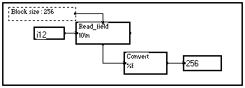
Jump module not connected
Meaning : A slave jump module is used in the MUSTIG graph, but the master jump module cannot be found. The most frequent causes are :
- The case of the characters are different in the master and slave jump module. Be aware that the jump modules are case-sensitive. An example of erroneous link is shown below.

- An invisible space sign has been accidentally inserted at the beginning or the end of the string in one or the jump modules.
This error also happens when using the Choice mouse interface module, if the name in the jump modules and the names in the Labels module (inside the mouse-sensitive box) are different. This process is case- and space-sensitive too.
Remedy : Check the names in the jump modules. If these seem strictly equal, look for hidden space signs in the names by moving the text cursor in the name with the arrow keys of the keyboard.
Length of variable forbidden
Meaning : The length of a variable is zero or less (-1 is allowed)
Remedy : Change your program so that the length of the variables is larger than zero. If the length is set to -1, the signal is infinite and the simulation is carried out until the user clicks in the MUSTIG window to stop it.
Library subroutine not found
Meaning : The program requires one or several macros (shown in red) that are normally taken from an additional MUSTIG library, but this library cannot be found.
Remedy : If the missing library is an official MUSTIG library (e.g. filter synthesis library, wavelets library, ...) or a custom one, add its path in the Edit / Options / Paths menu (right column). The gray buttons on the left allow to browse the directories to locate the missing library : click on any file in the directory to add the corresponding path to the list.
If this error occurs though only the basic library is required, check that the following sub-libraries are present in the Mustig directory :
- Library.mtg
: MUSTIG standard library
- Doc.mtg
: General help file
- Compat_4.mtg
: Allows compatibility with previous versions
- Views45.mtg
: Contains the output modules for the 4.5 and subsequent versions.
These four sub-libraries should be present. Some may have been deleted or renamed accidentally, or incorrectly decompressed by the installation program.
Compressed files feature an underscore (_) sign in their extension. To decompress a file, move to the appropriate directory and type :
expand file.mt_ file.mtg
The expand program is normally installed in the Mustig directory.
If none of the sub-libraries has been decompressed (installation program aborted or defective), launch the recuprep.exe program. A batch file is created : run it to decompress all the files.
Mixing signals with different characteristics along (variable name)
Meaning : You are trying to add, subtract, multiply or divide two signals depending on the same variable, but having a different length : this is impossible.

Remedy : Change your program so that both signals have the same length before carrying out an arithmetic operation on them.

Remember that you may carry out such operations if the variables have a different length AND a different name. In this case, MUSTIG performs the calculation on every combination of samples of these signals and the results is thus a matrix (see Functional mode).
Tip : To know the attributes of the signals on the input pins of the module, slide an Info module (available in the Variable changes section of the Library) into the program window. Click on it to select it and launch the Probe mode (Alt+R shortcut) : the mouse cursor changes into a probe. Click on each input wire by turns to see the characteristics of the variables : the differences are easily detected. Hit Alt+R again the return to normal mode. The probe mode may be used with any module, macro or box having one input pin and no output pin (see Probe mode).
Mustig license does not exist on this machine
Meaning : You are trying to run Mustig with an invalid Mustig4.cle key file. This file must be included in the Mustig directory and should not be renamed. Possible causes are :
- Wrong protection dongle number
- Wrong machine number
- Outdated Mustig4.cle file (for temporary versions)
Remedy : Check that the host_id number of your machine is equal to the machine number in the Mustig4.cle file. Check that the protection dongle is present. Check that the Mustig4.cle file is present in the Mustig directory and has not been renamed or changed. If you are using a temporary version, check the date in the Mustig4.cle file.
If case everything seems correct, contact the online help service for further assistance.
Number of pins is incorrect
Meaning : Internal Library error. You may get this error if you use macros from very old versions of MUSTIG.
Remedy : If possible, replace the macros by a more recent, equivalent macro. If not, report this error to the online help service.
Number of variables or variable name incorrect
Meaning : You are probably trying to create a macro, but the variables names you have entered on the front panel (so that they can easily be modified) are unknown inside the macro. Thus, the operation is cancelled and the variables are removed from the front panel of the macro.
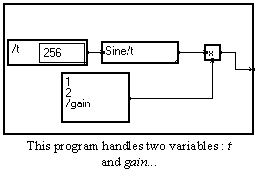


Remedy : Enter the text edit mode in the front panel (Shift+Ctrl+Click) and enter variable names that exist inside the macro.

Note : Once the macro is correctly defined, you may change a variable name to adapt to the variables defined in your application :

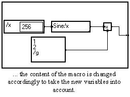
Only one infinite (length = -1) variable is allowed
Meaning : Two variables are declared with an infinite length. This is not allowed.

Remedy : Change your program so that only one infinite variable is used.

Open error
Meaning : Mustig cannot open or save the file. The most common cause is trying to save a graph in a directory into which you do not have the right to write files.
Remedy : Either save the graph in another directory using the Save as... command from the File menu, or contact your system administrator to obtain proper access rights.
Operation not supported on a dynamic length variable
Meaning : You are trying to carry out an operation on a signal which length changes dynamically according to another variable, and this operation does not accept dynamic variables. The Undersampling module in the example below is one of these modules that do not accept dynamic variables.

Remedy : Use modules that accept dynamic variables, or change your program to (at least temporarily) fix the length of the signals. This is done by saving the original lengths of the signals, zero-pad all the signals to the maximum length, processing these fixed-length signals, and then cutting the signals dynamically back again to the appropriate lengths, like in the example below.
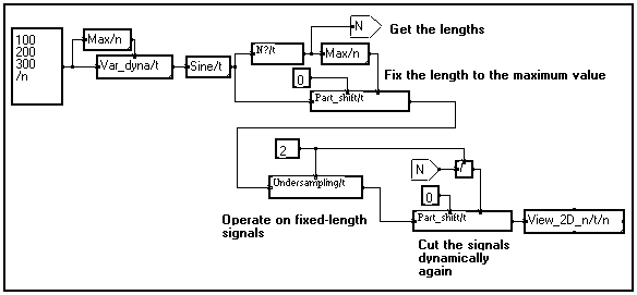
This is a common way of overcoming the restrictions on the use of dynamic variables.
Operation on a variable which controls the length of another variable of the same signal (variable name)
Meaning : This is a restriction on the use of dynamic variables. You are trying to carry out an operation according to a variable that controls the length of the signals, and this operation is not possible.
In the example below, one tries to mirror a cluster of signals (t is the time and n the signal number) which length changes dynamically, to reverse the order of the signals in the cluster (the first signal becomes the last, and so on). This operation cannot be done because the signals do not have the same length.

Remedy : Use modules that accept dynamic variables, or change your program to (at least temporarily) fix the length of the signals. This is done by saving the original lengths of the signals, zero-pad all the signals to the maximum length, processing these fixed-length signals, and then cutting the signals dynamically back again to the appropriate lengths, like in the example below.
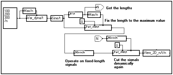
This is a common way of overcoming the restrictions on the use of dynamic variables.
Pin not connected
Meaning : The input pin shown in red is necessary for calculating the result, but it is not connected. If the pin seems connected, then the unconnected pin should be sought for upstream (here in the x16 macro) :


Remedy : Open the upstream macro until you find the unconnected pin, and connect it correctly.


This error may occur in other cases :
- Several input pins are connected together but are not connected to an output pin
- An input pin is connected to a slave jump module which is not associated with a master jump module. Check for spurious spaces or carriage returns following the names on the jump modules. This may occur in particular in the Choice mouse interface module. Be aware that the process is case-sensitive.
- The number of pins or the labels on a bunch module is incorrect. Be aware that the labels are case-sensitive :
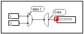
Read error
Meaning : An error occurred when trying to read data from the disk.
Remedy : Try read the data again.
Respect hierarchy for images
Meaning : You are trying to slide a module onto the front panel of a macro or onto an Image window to create an interactive image of this module (see Creating images), but the module does not belong to this macro, or is not in the same graph as the Image window.
In the example below, this error occurs if you try to slide a module from the Macro1 macro onto the front panel of the Macro2 macro, or conversely.

Remedy : Create images of modules from the macro only, or from sub-macros included in the macro. If you want to mix images of modules from several macros, gather these macros into a single macro first.
In the above example, you could create a box to frame Macro1 and Macro2 and hit Alt+M to create a "mother" macro. You may then slide modules from both Macro1 and Macro2 into the front panel on this new macro.
Signal length not equal to a power of 2 (variable name)
Meaning : A Fast Fourier Transform has been programmed (TF/t/f module), and thus the length of the variable should be a power of 2 at this point of the graph.

Remedy : Use a Part or similar module to cut or extend the length of the signal to a power of 2 - The Round to 2**n module in the Elementary operations section of the Library allows to calculate the nearest larger power of two from the signal length.
You may also use the DFT Discrete Fourier Transform macros in the Complex section of the Library : they do not require the signal length to be a power of 2. However, they are much slower than the Fast Fourier Transform.

Signal length not equal to a power of 2 + 1 (variable name)
Meaning : A Fast Inverse Fourier Transform (TFI/f/t module) is called. Thus, the signal length should be a power of two plus one (e.g. 129, 257, 513, ...) if its Half attribute is 1.
In particular, this is the case if the signal is a complex signal obtained by calculating the Fast Fourier Transform of a real signal, like in the elementary low-pass filter below. The Inverse Fast Fourier Transform of such a signal is a real signal.

Remedy : Use a Part or similar module to cut or extend the length of the signal to a power of 2 plus one before entering the Fast Inverse Fourier Transform - The Round to 2**n module in the Elementary operations section of the Library allows to calculate the nearest larger power of two from the signal length.
You may also use the IDFT Discrete Inverse Fourier Transform macros in the Complex section of the Library : they do not require the signal length to be a power of 2 plus one. However, they are much slower than the Fast Inverse Fourier Transform.

Structure error
Meaning : The graph cannot be saved because of an internal error.
Remedy : Try deleting by turns the modules you had recently added to the graph, until it can be saved again. Report this error to the online help service.
Structure not calculable
Meaning : The MUSTIG compiler cannot process this graph. The probable cause is the graph having circular dependencies more complex than those detected by the Vicious circle error (see Vicious circle).
Remedy : Modify your program to suppress the circular dependencies.
Syntax error
Meaning : The text shown red-framed features a syntax error. This may occur when entering an interface text in the Extern or Fortran module, when entering a formula in the Formula module, or when writing a Batch script.
Remedy : Correct your text to remove the syntax error.
The box must have only one (entry) pin
Meaning : You are trying to use the Probe mode (Alt+R shortcut) with a module not having the proper characteristics : only one input pin, and no output pins :

Remedy : Create a box around the module (Click+Slide), create a pin on the box (Shift+Click), and connect the pin to the input pin of the module :

Click on the box and hit Alt+R again to use the Probe mode.
The library cannot be saved this way (FileName.bib)
Meaning : When a program previously saved with the Library format (Save special command) is opened for the first time, MUSTIG creates a special file with a .bib extension. This error occurs if MUSTIG cannot write this file. It does not prevent MUSTIG from working correctly. The most common cause is running MUSTIG under Windows NT or UNIX with inappropriate access rights.
Remedy : Launch MUSTIG once with correct user privileges, so that it can write the .bib file to the Mustig directory - Change the access rights of the user in the Mustig directory.
Be aware that if you don't have the proper access rights, the Mustig.prf option file cannot be saved : MUSTIG will always start with the default options.
The signal does not depend on the variable (variable name)
Meaning : You try to perform an operation according to a variable which does not exist at this point of the graph. In the example below, a variable named x is created and one tries to build a sine wave according to a variable named t : this is an error.

Remedy : Change the name of the variable on the front panel of the selected module (Click on the name, or Shift+Ctrl+click if the box is not locked). The name will be automatically changed in all the inside sub-macros. Also see the tips below.

All the modules inside the Sine/x macro, that previously depended on variable /t, now depend on variable /x. You can see this by double-clicking on the macro twice :
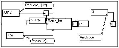
This technique allows to change the name of the variable according to which a macro should operate, without changing the name in all the sub-macros it contains.
Tip 1 : If several variable names should be changed, delete all the variable names, and then enter the new names in the same order. This prevents accidentally replacing two variables by a single one :


Tip 2 : If you want to change the variables that can be renamed from the front panel (e.g. change the number of variables that can be accessed this way) : delete all the variables from the front panel and click outside the box to exit. Then, re-enter the edit mode and enter the variables you want the user to have access to :


Tip 3 : If the user renames a variable on the front panel into the name of an internal variable (used inside the macro but not present on the front panel), the internal variable is automatically renamed by inserting a ">" sign before the name, in order to avoid having inconsistent variable definitions.


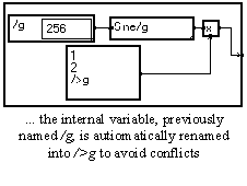
The variable definitions must be static
Meaning : This input parameter must be static, i.e. it should not depend on another variable. A typical case is trying to define several sampling rates or origins for a signal (see example below). Some modules from the library do not support dynamic variables and produce this message when used with dynamic signals.
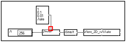
Remedy : Modify your graph so that the variable definition become static.

This pin must be isolated with a "=" module
Meaning : Two pins are connected in a configuration that is not permitted. This may happen particularly when using programs created with older versions of MUSTIG. Such invalid configuration may also be obtained with the clustering modules :
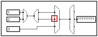
Remedy : Insert a "=" module (available in the Elementary Operations section of the library) just before the pin in question.
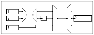
The "=" module does nothing with the data, but acts as an intermediate connector required in such cases.
Too many windows
Meaning : Too many windows are open in the same time.
Remedy : Close some windows and some unused MUSTIG programs. It might be necessary to save the graph after closing all the windows, exit MUSTIG and rerun it again.
Try to loop a signal having a variable which length depends on the loop variable
Meaning : A loop is performed according to a variable (here variable i in the Sum/i macro), but the length of the signal changes dynamically according to this variable : this is not permitted.
In the example below, the error occurs because one tries to sum according to variable i three signals of length 100, 200 and 256 samples along variable t, which is impossible (you cannot sum a 100-sample vector and a 200-sample vector !).

Remedy : Change the graph so that all the signals have the same length, or sum according to a variable according to which this operation is valid.

Note : Summing according to variable t would be OK and would produce a vector (along variable i) of three sums.
Unknown code
Meaning : Internal error.
Remedy : Report this error to the online help service. If possible, email a copy of your program so that it can be run with a debugging tool.
Vicious circle
Meaning : The graph cannot be calculated because it is circular. This error frequently occurs when one forgets to insert a delay in the algorithm (here a first-order filter).

Remedy : Modify the graph (e.g. by inserting a delay operator) to break the circular dependence.

Write error
Meaning : An error occurred when trying to write data onto the disk.
Remedy : Try writing the data again, or write it onto another disk.
DEBUGGING TIPS
Some wires disappear, the graph looks inconsistent
Sometimes the graph looks inconsistent, as if a wire had disappeared :
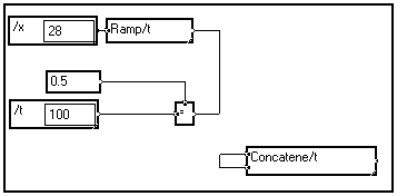
It simply means that two wires are superimposed. As the XOR operation is used to handle superimposition, two superimposed wires are drawn as an invisible wire ! In some versions, superimposed wires are displayed as a normal, single wire, causing the graph to look inconsistent as well.
Just place the mouse cursor over the invisible wire and move it a bit to separate the wires :
I cannot print any Mustig window
Surely the print options are not correct.
- Check that your printer works properly.
- Check the options in the File / Page setup menu.
- Check the options in the Edit / Options / Graphics menu : maybe the Print in an .eps file option is on.
A few print errors have been observed with some printers, especially networked printers. Contact the online help service for more information.
The Cut / Paste facility does not work properly with other applications
Some applications do not accept high-resolution Cut/Paste. Checking the Edit / Options / Graphics / bitmap copy option produces a bitmap that is generally well accepted. Also try to change the Edit / Options / Graphics / Copy the border of the selected box option.
All the windows of all the macros opened at a time !
You probably right-clicked in the main MUSTIG program window : all the boxes and sub-macros have thus been calculated at once ! You may prevent this by checking the Edit / Options / Do not calculate the whole main graph option.
The results do not update
When a modification is performed in the graph, the results are updated or merely reset, depending on the value entered in the Edit / Options / Calculations / Time threshold for automatic recalculation field.
A small value indicates that MUSTIG should recalculate only the results needing a brief calculation time, and just reset results needing longer calculations. For data acquisition programs we strongly recommend that you set this value to 0, to prevent launching acquisition runs accidentally when an input value is modified.
- If you want all the results to be automatically recalculated, no matter how much time it takes, check the Automatic recalculation in the Calculations menu. This option should not be used when running data acquisition programs.
- You may update a window or a box manually by clicking on the Recalculate option in the Calculations menu.
All the graphical results are in black and white
Surely the Edit / Options / Graphics / Black & white palette is on. Clear the program by clicking on the main program window and launching the Clear the box command from the Calculations menu. Then, go to the Edit / Options / Graphics window and change the palette option.
I cannot drag a module from a Mustig window
When a window or a box is locked, you cannot drag a particular module from there to drop it somewhere else. In order to do this, either
- unlock the box using the Alt+W shortcut,
- or use Shift+Click instead of Click to drag a particular module.
If you can drag the module but MUSTIG does not accept to drop it in the destination box, it means that the operation you are trying to perform is invalid :
Creating an image of a module into a panel which does not belong to one of its mother-macros,
Trying to drop an Image window into a macro instead of the main program window,
Dropping a module into a locked window,
are examples of invalid operations.
The options file is not saved when exiting Mustig
MUSTIG cannot write the options file into the MUSTIG directory : you probably do not have the proper access rights to the MUSTIG directory.
The program shortcuts (File menu) do not work
You probably do not have the proper access rights to the MUSTIG directory.
The option I have set is not taken into account, or is not accepted
Some option require the MUSTIG program and the memory to be cleared before changing them.
- Click in the main MUSTIG program window to select and launch the Clear the box command from the Calculations menu. Then, try changing the option again.
- If this does not work, try closing the program and opening it again.
- If still inefficient, try exiting MUSTIG and changing the options before opening your program.
- If the option is still not accepted, maybe it is not valid : maybe you require more memory than available, or maybe the option is not supported on your computer. Contact your online help service.
There are some graphical artifacts in the MUSTIG windows
If graphical artifacts appear in a MUSTIG window when moving or resizing a box, move the window to the bottom of your screen, drop it, and move it back to its original place to force an update.
You may also simply resize the window to force the update, but this is not recommended when the window is locked.
Only a portion of a curve is displayed
This has been observed sometimes (though rarely) : a graphical curve is displayed with a random offset in the graphical window, and thus only a portion of the curve is visible.
This is generally solved by closing the window and calculating it again. In some cases it is necessary to clear the program, or to close it.
If this behavior is often observed with your application, please contact the online help service and send a copy of your program if possible.
![]()
![]()

![]()


