INTERFACING EXTERNAL ROUTINES WITH MUSTIG
Table of Contents
5-2. Defining the interface in MUSTIG
5-3. Special Macintosh features
5-6. Special PC + AU32 features
5. Interfacing external routines with MUSTIG
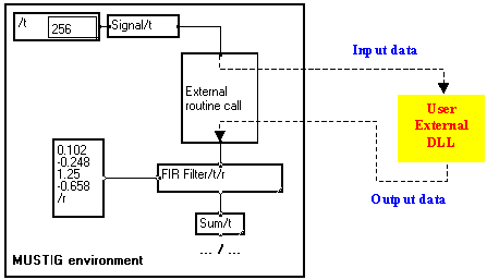
External routines may be called from a MUSTIG graph :

Input data (e.g. signals, numerical parameters, strings, variable description) are defined in MUSTIG and passed to the external routine. The latter processes the incoming data and generates output data that are passed again to MUSTIG for further processing or display.
The output data is not required to have the same structure than the input data. For instance, you may define a 2D signal, plus a vector of parameters, plus a string as input parameters, and generate only a scalar on the output.
This allows to use existing custom routines without having to rewrite them completely in MUSTIG language. Some algorithms are more easily written in a procedural language like C than in MUSTIG. In such cases, it may be a better idea to create and interface an external routine, than to build a MUSTIG graph that does the same job.
5-1-2. Constraints on the external code
On some machines (e.g. Macintosh 680xx or Sun/OS), the code must have only one entry point : you cannot use multiple-entry DLLs.
Of course, the code needs to be slightly modified to allow input and output communication with MUSTIG (see Defining the interface in the external code).
5-2. Defining the interface in MUSTIG
Extern moduleThe external interface module is available in the <-> section of the library :
|
|
Allows to interface a C program with MUSTIG |
|
|
Allows to interface a Fortran program with MUSTIG |
The module initially has 8 pins, numbered clockwise from 1 to 8 :

You may add or remove pins if necessary (see Creating a pin and Deleting a pin) : the pins are renumbered clockwise, starting at the lowest pin on the left edge of the module.
The structure of the input and output data will be described as a text entered in the front panel of the module. You may resize the module if necessary. Each pin may be used as an input pin or as an output pin, depending on how it is labelled in the text.
5-2-2. Defining the function of the pins on the
Extern module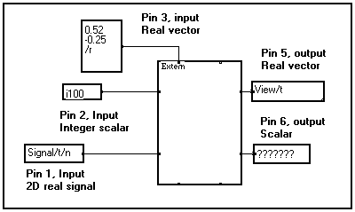
You now visualize the type and structure of the data on each pin.
If this name is My_Subprog for instance, MUSTIG will look for an external routine named My_Subprog, My_Subprog.sub or My_Subprog.dll first in the current directory, and then in the directories specified by the user in the Edit / Options / Paths window and in the environment variables.
The name may also be an entry in a multiple-entry DLL (if available on your machine). For instance, the name
My_dll@My_Routine
refers to a routine named My_Routine in the DLL named My_dll.dll.
<pin number><direction><data type>[<associated variable(s)>]
|
Field |
Possible values |
Function |
|
<pin number> |
1 to total number of pins |
Number of the pin (see The Extern module) |
|
<direction> |
+ : output pin - : input pin |
Sets the direction of the pin (input or output) |
|
<data type> |
I1,I2, I4 for integers R4, R8 for reals C8, C16 for complexes W for a graphical plane S for a string X indifferent type (see below) |
Sets the type of data on the pin. See the examples provided with Mustig for a demo of how a graphical plane should be processed. |
|
<associated variable(s)> |
If the data are not scalar, the name of the variable(s) is specified after a '/' sign as usual. |
|
Indifferent "X" type :
If the external routine generates an output signal (i.e. a vector, a matrix, a 3D signal, …), this signal must be carried by at least one variable. If the output signal has exactly the same attrubutes than an input signal, the same variable name may be used (see Attributes of a variable).
However, if the attributes of an output signal are different than those of one of the input signals, a appropriate variable description must be entered on an input pin of the Extern module. The associated line on the front panel of the module is entered with a type equal to X, meaning that only the attributes of the variable are used, not the data it carries if any.
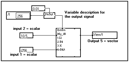
In the above example, the external DLL is called with two scalars as input data, and returns a vector. The user must tell MUSTIG what the characteristics of the generated vector are, by adding an input pin (pin #3 here) connected to a variable description with appropriate attributes. This description may be picked up from an existing signal : only the attributes will be used, not the data themselves.
Please note that an "X" pin must not be referenced in the external DLL code, it is only used by Mustig.
Example
If one assumes that the output scalar is a real number, the interface text for the example presented in paragraph 1 could be :
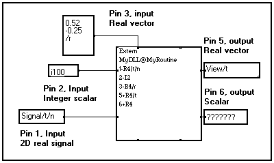
Other examples of valid interface lines
|
1-C8/x/y |
Pin #1 is an input pin, carrying single-precision complex data distributed as a 2D signal depending on variable x and y. |
|
3-X/u |
Pin #3 is an input pin, carrying the description of a variable named u. This variable will be used for building an output signal. |
|
6+S |
Pin #6 is an output pin returning a character string |
|
1-W |
Pin #1 is an input pin carrying a graphical plane |
|
4+I2/t |
Pin #4 is an output pin returning a vector of 2-byte integers described by a variable named t. |
Following the description of the pins in the interface text, the user may enter one or both of the following letters :
|
IX |
Usually, if the available memory is insufficient to process a signal, the external routine may be called several times by Mustig. If the X flag is present in the interface text, this process is disabled. Use this flag when interfacing MUSTIG with data acquisition routines. |
|
5-2-3. Interface code to add to the DLL
The process of interfacing an external routine with MUSTIG has been described above from MUSTIG's point of view.
In this section, we describe how the interface is written from the point of view of the external code : the external code must know where are the input data and where to store the output results. This section requires that the reader be familiar with the notions of pointer and memory address.
Of course, the name of the pointers and variables may be different than those presented in the following sections. You are free to choose more explicit, or more compact names if you wish.
Pointers used for referring to the data table
When entering the external routine, the stack contains three pointers :
|
Name |
Points to |
Function |
|
t |
Mustig's data table |
First address of the data table |
|
p |
The parameter table (see below) |
Refers to the pins |
|
r |
An 80-character string |
Error message to return |
The parameter table is made of long 32-bit integers.
C language : The parameter table is declared as a structure p of long integers, and the elements described below are the components of the structure. (see the example).
Fortran language : The parameter table p and its components (i.e. the variables listed below) are declared as integer*4 variables. For each pin, the user calls a specific subroutine named mstg#v, where # stands for the number of variables on the pin (see the example)
|
Var. Name |
Function |
|
i |
Reserved index (initialized to 2) |
|
nb_pins |
Number of connected pins - Allows to check that the number of connected pins is correct - If nb_pins is found to be equal to 0, it means that the "I" option has been entered in the interface text of the Extern module and the external routine is called again when the calculations are over (see Optional call modes). The pins declared as X type in the MUSTIG Extern module are not included in this count. |
|
Var. Name |
Function |
|
nvar# |
Number of variables (or dimensions) carried by the pin :
|
|
d# |
Position in the data table pointed to by pointer t. |
|
Var. Name |
Function |
|
in# |
An increment between consecutive values along the variable |
|
n# |
Number of samples along this dimension |
Example of potential variable declaration
:|
nvar0, d0 |
Pin #0 carries a scalar. Thus, nvar0 will be set to 0 (no variable) by Mustig when calling the external routine. We recommend that this be checked in your code. |
|
nvar1, d1, in1, n1 |
Pin #1 carries a vector (i.e. the signal there has one variable). Thus nvar1 will be set to 1 by Mustig. |
|
nvar2, d2, in2, n2, in21, n21 |
Pin #2 carries a matrix (i.e. the signal there has two variables). Thus, nvar2 will be set to 2. |
|
nvar3, d3, in3, n3, in31, n31, n32, in32 |
Pin #3 carries a 3D signal (i.e. the signal there has three variables). Thus, nvar2 will be set to 3. |
Note : In these variable declarations, the pins are numbered from 0 to Npins -1. You may change this and number the pin from 1 to Npins if you want. Just change the variable names accordingly. The names of the variables are not used as keywords, so you may give them the names you want.
Referring to data in the external C code
Pointer t can be seen as the address of the first element of a large memory segment : the so-called Mustig data table.
The data carried by each pin (either input of output) is referred to using the previously declared variables d# (see The parameter table) which gives the offset of the data segment on each pin :

Case 1 : the pin carries a scalar
value = *(t + p->d0);
Where value is a variable of the same type than that declared for the pin in the interface text on the Extern Mustig module. Otherwise, automatic conversions will be made by your computer and the result may not be well portable to other machines.
*(t + p->d0) = value;
*(t + p->d0) = 0.5213;
Note : You may also use intermediate variables and pointers to refer to the pin, if you find it more readable :
int *pin_0; /* declare an intermediate pointer */
pin_0 = (t + p->d0); /* that refers to pin #0 */
value = *pin_0; /* Read it if it is an input pin */
pin_0 = value; /* or write if it is an output pin */
Case 2 : the pin carries a vector
Suppose that pin #0 carries a vector. This vector is given a memory segment starting at address
t + p->d0
This address corresponds to the first element of the vector. To read or write other elements of the vector, use the previously declared in# increment variable, which gives the number of bytes between two consecutive elements of the vector :
|
t + p->d0 |
Address of the first element = vector[0] |
|
t + p->d0 + in0 |
Address of the second element = vector[1] |
|
t + p->d0 + n*in0 |
Address of the nth element = vector[n] |
Exemples :
|
val = *(t + p->d0 + 2*in0) |
A previously declared variable named val is set to the value of the third element of the vector on input pin 0. |
|
*(t + p->d0 + 2*in0) = val |
The third element of the vector on output pin 0 is set to the value of variable val. |
|
vector = t+p->d0 |
1D pointer vector is associated with pin 0 |
Case 3 : the pin carries a matrix
Following the same principle, if the pin carries a matrix, you may refer to any element by using the increment variables on both dimensions. Use this address to read or write data as usual.
|
t + p->d0 + i*in0 + j*in1 |
Address of the element located at the ith position along the first variable and at the jth position along the second variable. |
The same technique is used if the signal on the pin has more than two dimensions.
5-2-4. Example of interfaced external routine in C and Fortran
The following example of external matrix processing is provided with Mustig :
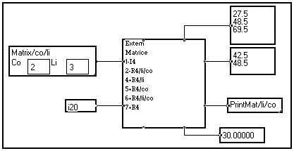
Here is the 3x2 input matrix on pin 1, entered by double-clicking on the Matrix/li/co macro :
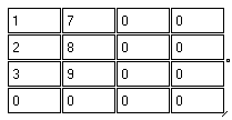
and here is the calculated 3x2 output matrix passed to pin 6 :

It has been calculated using the following algorithm written in the external routine :
The following results are calculated by the external routine and passed to the output pins :
|
Pin 4 |
Second column of the calculated output matrix |
|
Pin 5 |
Second row of the calculated output matrix |
|
Pin 6 |
Calculated output matrix |
|
Pin 7 |
Sum of the elements of the input matrix |
The C code of the external routine is given below : the comments explain how the parameters are actually recovered.
/* Example of external << C >> routine */
/*
IMPORTANT NOTE
In this external routine, the pins are referred to using variables which contain a "pin number". These pin numbers range from 0 to the number of CONNECTED pins minus 1.
In Mustig, the Extern module numbers the pins from 1 to the number of EXISTING pins (either connected or not) and some pins are not connected.
Therefore, pin N in this code does NOT correspond to pin N as it is numbered on the interface text of the Extern Mustig module
*/
void__export matrice(t,p,r)(t,p,r)
char *t; /* Pointer to the Mustig data table (array) */
char *r; /* String to return potential error messages */
struct {long /* Parameter table */
i, /*index initialized to "2" */
nb_pins, /*number of pins used*/
/*pin 0, scalar input, integer on 4 octets*/
nvar0, /* number of variables support of signal on
the pin (should be 0) */
d0, /* offset in array t */
/*pin 1,matrix input, real*/
nvar1, /* number of variables support of signal on
the pin (should be 2) */
d1, /* offset in array t */
in1, /* increment on the first dimension */
n1, /* number of values */
in12, /* increment on the second dimension */
n12, /* number of values */
/*pin 2,vector output, real*/
nvar2, /* number of variables support of signal on
the pin (should be 1) */
d2, /* offset in array t */
in2, /* increment */
n2, /* number of values */
/*pin 3,vector output, real*/
nvar3, /* number of variables support of signal on
the pin (should be 1) */
d3, /* offset in array t */
in3, /* increment */
n3, /* number of values */
/*pin 4, matrix output, real*/
nvar4, /* number of variables support of signal on
the pin (should be 2)*/
d4, /* offset in array t */
in4, /* increment on the first dimension */
n4, /* number of values */
in42, /* increment on the first dimension */
n42, /* number of values */
/*pin 5, scalar output, real*/
nvar5, /* number of variables support of signal on
the pin (should be 0) */
d5; /* offset in array t */
} *p;
/* End of the description of the pointer to the parameter list */
/* Begin the main program */
{
static float value=0.5;
int err,i,j;
float *a,*b,*a0,*b0,*v1,*v2;
long val0;
float fval0,*afval5,s;
long n1,n2,inc1,inc12,incv1,incv2,inc4,inc42;
/* Check the input data and declare intermediate variables */
if(p->nb_pins != 6) {strncpy(r,"wrong number of connected
pins,80);return;}
/*pin 0*/
if(p->nvar0 != 0){strncpy(r,"Connected Pin 0 not a scalar",80);return;}
val0=*((long*)(t+p->d0));
fval0=val0;
/*pin 1*/
if(p->nvar1 != 2){strncpy(r," Connected Pin 1 not a matrix",80);return;}
a0=(float*)(t+p->d1); /*address of input matrix*/
n1 = p->n1; /* number of matrix points along 1st dimension */
n2 = p->n12; /* number of matrix points along 2nd dimension */
inc1 = p->in1; /* increment of matrix points along 1st dim */
inc12 = p->in12; /* increment of matrix points along 2nd dim */
/*pin 2*/
if(p->nvar2 != 1){strncpy(r," Connected Pin 2 not a vector",80);return;}
v1=(float*)(t+p->d2); /* address of first vector output */
if(p->n2 != n1){strncpy(r,"error vector-matrix",80);return;}
incv1 = p->in2; /* increment of vector points */
/*pin 3*/
if(p->nvar3 != 1){strncpy(r," Connected Pin 3 not a vector",80);return;}
v2=(float*)(t+p->d3); /* address of second vector output */
if(p->n3 != n2){strncpy(r,"error vector-matrix",80);return;}
incv2 = p->in3; /* increment of vector points */
/*pin 4*/
if(p->nvar4 != 2){strncpy(r," Connected Pin 4 not a matrix",80);return;}
b0=(float*)(t+p->d4); /* address of output matrix */
inc4 = p->in4; /* increment of matrix points along 1st dim */
inc42 = p->in42; /* increment of matrix points along 2nd dim */
/*pin 5*/
if(p->nvar5 != 0){strncpy(r," Connected pin 5 not a scalar",80);return;}
afval5=(float*)(t+p->d5);
s=0;
/*calculation of the output matrix from the input matrix */
for(i=0;i<n1;i++){
a=a0;
b=b0;
for(j=0;j<n2;j++){
*b= *a + fval0 + value;
s += *a;
a += inc12;
b += inc42;
}
value += fval0;
a0 += inc1;
b0 += inc4;
}
*afval5=s; /*result on pin5 is the sum of the terms of the input matrix*/
/*calculation of first vector = second column of matrix b*/
b0=(float*)(t+p->d4);/*address of output matrix*/
b=b0 + inc42;
for(i=0;i<n1;i++){
*v1 = *b;
v1 += incv1;
b += inc4;
}
/*calculation of second vector = second line of matrix b*/
b=b0 + inc4;
for(i=0;i<n2;i++){
*v2 = *b;
v2 += incv2;
b += inc42;
}
}
The FORTRAN code for the same external routine is given below :
c example of external routine FORTRAN
program MATRIX(t,p,r)
c systematic declarations for Mustig interface
integer*4 p
integer*1 t(0:1)
integer*1 r(80)
c declarations required for every declared pin
c - an address
c - for each support variable :
c - an increment
c - a number of values
c
integer*4 ad0,ad1,ad2,ad3,ad4,ad5,inc1,nv1,inc12,nv12
integer*4 inc2,nv2,inc3,nv3,inc4,nv4,inc42,nv42,ierr
external SPMATRIX
integer SPMATRIX
c a call to 'mstg0v' or 'mstg1v' or 'mstg2v'
c for each pin declared in the MUSTIG module
c pin 0
call mstg0v(p,ad0,ierr)
if(ierr .NE. 0) GOTO 100
c pin 1
call mstg2v(p,ad1,inc1,nv1,inc12,nv12,ierr)
if(ierr .NE. 0) GOTO 100
c pin 2
call mstg1v(p,ad2,inc2,nv2,ierr)
if(ierr .NE. 0) GOTO 100
c pin 3
call mstg1v(p,ad3,inc3,nv3,ierr)
if(ierr .NE. 0) GOTO 100
c pin 4
call mstg2v(p,ad4,inc4,nv4,inc42,nv42,ierr)
if(ierr .NE. 0) GOTO 100
c pin 5
call mstg0v(p,ad5,ierr)
c test of parameter coherency
100 if (ierr .NE. 0)then
call mstger(r,'Incoherent call')
return
endif
if(nv1 .NE. nv2) GOTO 200
if(nv12 .NE. nv3) GOTO 200
if(nv1 .NE. nv2) GOTO 200
if(nv1 .NE. nv4) GOTO 200
if(nv12 .NE. nv42) GOTO 200
GOTO 300
200 call mstger(r,'Lengths are incoherent')
c call calculation subroutine
300 ierr= SPMATRIX(t(ad0),
1 t(ad1),inc1,nv1,inc12,nv12,
2 t(ad2),inc2,
3 t(ad3),inc3,
4 t(ad4),inc4,inc42,
5 t(ad5))
c test return; error message if needed
if (ierr .NE. 0)call mstger(r,'Too large size')
end
c Utility subroutines : mstg0v,mstg1v,mstg2v and mstger
INCLUDE Mustig_inc.for
c calculation subroutine
integer function SPMATRIX(a0,
1 a1,inc1,li,inc12,co,
2 a2,inc2,
3 a3,inc3,
4 a4,inc4,inc42,
5 a5)
integer*4 inc1,li,inc12,co
integer*4 inc2,inc3,inc4,inc42
integer*4 a0
real*4 a1(0:1)
real*4 a2(0:1)
real*4 a3(0:1)
real*4 a4(0:1)
real*4 a5
integer*4 ada1,ada2,ada3,ada4,i0,j0
real*4 value,s,fval0
if ((li.GT.1000).OR.(co.GT.1000)) then
SPMATRIX=1
return
endif
fval0=a0
value=0.5
ada2=0
ada3=0
s=0
i0=0
j0=0
c calculation of the result matrix from the data matrix
do 10 i=1,li
ada1=i0
ada4=j0
do 20 j=1,co
a4(ada4)=a1(ada1)+value+fval0
s=s+a1(ada1)
ada1=ada1+inc12
ada4=ada4+inc42
20 continue
value=value+fval0
i0=i0+inc1
j0=j0+inc4
10 continue
a5=s
c calculation of the 1st output vector = 2nd column of the output matrix
ada4=inc42
ada1=0
do 30 i=1,li
a2(ada2)=a4(ada4)
ada2=ada2+inc2
ada4=ada4+inc4
30 continue
c calculation of the 2nd result vector = 2nd line of the output matrix
ada4=inc4
do 40 i=1,co
a3(ada3)=a4(ada4)
ada3=ada3+inc3
ada4=ada4+inc42
40 continue
SPMATRIX=0
end
5-3. Special Macintosh features
The external code must be a MUEX-type resource. Its name must be similar to that entered on the front panel of the Extern module. The file containing this resource may be in the Mustig directory or in the MUSTIG overlays directory.
The code must be self-consistent and may have been produced by any language (Pascal, C, ...), providing external libraries are not used. The environment a call time must be restored when the external processing is finished.
You may run the external routine usung the THINK-C symbolic debugger : follow the instructions in the Examples with externals / Debug Mustig / Doc Debug file.
You may interface Fortran routines with MUSTIG using the ABSOFT FORTRAN 020 development environment and the Fortran Mustig module. The latter is used exactly the same way as the Extern module. See External Fortran routine for an example of interface from the point of view of the code. Also see the Sum and Draw examples in the MUSTIG overlays directory.
You may use the Absoft Fortran symbolic debugger : follow the instructions in the Examples with externals / Debug Mustig / Doc Debug file.
The difference between using the Fortran module and using the Extern module is the following :
You may build multiple-entry DLL. See the matrix example and the associated THINK-C project.
The structure of the routines is similar to that described in the previous sections. However, two load modes are available :
Note : This old-fashioned load mode has been preserved to ensure full compatibility with the programs developed using previous versions of Mustig. However, the dynamic load mode is recommended.
This mode requires a large segment of the shared memory to be created in order MUSTIG to build the data table. Therefore, make sure the configuration of your system allows creating segments of sufficient size in the shared memory. The default size is 4Mbytes, other values may be entered in the Edit / Options menu.
The Extern and Fortran modules are equivalent in this mode.
This mode is set by clicking on the Shared memory externals box in the Edit / Options menu.
The entry point must be named main_ext :
subroutine main_ext(t,p,r)
integer*4 p
integer*1 t(0:1)
integer*1 r(80)
.
.
main_ext(t,p,r)
char *t;
char *r;
struct {long
i,
nb_bornes,
nvar1,
d1,
nvar2,
d2,
in2,
n2;
} *p;
.
.
Compiling the external routine
The routines must be linked to a sub-program delivered with Mustig :
main_ext_f.o for FORTRAN routines
main_ext_c.o for C routines
Examples of link commands are :
cc -o My_routine main_ext_c.o My_Routine.c
cc -o My_routine main_ext_f.o My_Routine.f
My_Routine is the created external routine : its name must be entered in MUSTIG on the front panel of the Extern or Fortran module.
Note : If an error occurs, it may be necessary to clean the segments using the ipcs and ipcrm UNIX commands.
On some machines, the number of times a routine may be called is limited to 16384.
This mode is set by de-checking the Shared memory externals option in the Edit / Options menu. It does not require a large segment of shared memory to be created. In order to allow the external routine to be managed by the Dynamic Link system, there are two differences from the shared memory process :
My_Routine(t,p,r)
char *t;
char *r;
struct { long
i,
.
.
This routine may be included in a My_Routine.c source file. In this case, the compiled My_Routine.dll routine will be sought for and used by MUSTIG.
cc_ext My_dll
to build the routine.
If the external routine requires a large amount of temporary memory to work, it is recommended that you reserve this memory in MUSTIG and pass it to the routine via an input pin : just reserve a vector or a matrix of sufficient size, and use this memory segment as a "work zone".
You may however allocate memory dynamically in the external routine, but make sure you check the return value of any memory allocation function. In case of memory overflow, you must return an error message to Mustig, to prevent it from using unallocated memory. Make sure to free to allocated temporary memory before returning to Mustig.
It is NOT recommended that you use large memory arrays on the stack, or declared as static in the external routine.
If the executable external routine has the ".dll" extension, the dynamic load process is enabled. Otherwise, the shared memory process is used.
Creating the ".dll" external routines
The cc_ext UNIX command file is delivered with Mustig. A non-exhaustive list of cc_ext commands is presented below :
|
SUN - OS |
cc -pic - $1.c ld -o $1.dll -assert pure-text $1.o |
|
SUN - Solaris |
cc -Kpic -c $1.c ld -z defs -G -o $1.dll -e $1 $1.o -lm -lc |
|
IBM RISC 6000 |
cc -c $1.c ld -o $1.dll -e $1 $1.o |
To create an external dynamic link routine, just select the 32-bit Windows DLL target in your compiler. Browse the available compiler options to spot possible default options that may unable creating the DLL correctly.
A 32-bit compiler is required to build multiple-entry Windows DLLs. Examples of DLLs created with the WATCOM 10.5 compiler are delivered with MUSTIG.
5-6. Special PC + AU32 features
The MUSTIG_AU32 version allows to monitor the OROS_AU32 TMSC320 DSP board directly from Mustig. The Mustig program is automatically transferred to the AU32 board at run time. This version allows to create custom real-time applications while taking advantage of Mustig's legendary user-friendliness and easiness of use.
The so-called Mixed version allows to switch between the AU32 board and the PC for running the programs : the user can tune up an application on the PC and send it to the AU32 board when ready.
You may create external routines in the AU32 version too : these will be automatically transferred to the OROS AU32 DSP board at run time. The Edit / Options / Calculations dialog box features two additional fields :
Important note : This memory amount, as well as the memory amount reserved for the code, may be changed only if no data is stored. Thus, it is necessary to clear the data by clicking on the program window and launch the Clear the box command in the Calculations menu.
.tms external routine for the AU32 boardIf the routine name entered in the Extern MUSTIG module is My_Routine, MUSTIG searches in the current directory for the executable My_Routine.tms file. The latter must have been produced by a My_Routine.c source file including the declaration
void My_Routine(t,p,r)
The command line used for building the My_Routine.tms routine is :
cl30 -g -mi My_Routine sub1 .... -z -r -cr -o My_Routine.tms -l \c30tools\rts30.lib
where sub1.c, ..., are the subprograms used by My_Routine.c.
Example
The matrix.c external routine (see Example of interfaced external routine) is provided as an example in the extern directory. Both executable routines matrix.dll (running on the PC) and matrix.tms (running on the AU32 board) must be in the same directory as matrix.mtg, the calling MUSTIG program.
The following files are available in the ext_tms subdirectory :